A High-Performance HF VFO using the AD9854 DDS IC
During the late 1990s, radio frequency homebrewers really began taking advantage of the conveniences that DDS technology offered: 1-chip simplicity, DC-to-30 MHz signal generation ability and relatively decent signal purity. Since then, Craig Johnson, AA0ZZ and others have been creating and refining signal generators using this technology. Craig began working with one of the latest DDS chips from Analog Devices, with an end goal of designing a 0-30 MHz VFO for use with the KK7B high-performance R2PRO receiver. This effort resulted in his taming the AD9854 dual-output (I-Q) DDS chip, and designing a pc board and working with the AmQRP Club to kit the project so others can easily build this modular, high-performance HF VFO for use on the bench.
In the July, 1997 issue of QEX magazine, WB2V published a landmark article featuring a signal generator which used an Analog Devices AD9850 DDS device controlled by a PIC16F84 microcontroller. The signal generator could be used as a VFO, of course. Those radios that need opposite sideband suppression could use this signal generator along with some type of hardware phasing techniques. This project generated a lot of interest and many spin-off projects.
Since that time, a newer device has been introduced by Analog Devices – the AD9854 – offering some significant advantages. First, the AD9854 has quadrature signal outputs – two signals are produced with exactly 90-degree phase difference. This phase relationship remains constant regardless of the frequency. When used in a DC phasing HF receiver or a single-sideband transmitter, these two outputs make it easy to provide opposite sideband suppression over a wide frequency range. The AD9854 data sheet specs a 0.2 degree maximum phase error.
Second, the AD9854 has a 12-bit D/A converter. This is important in reducing the undesirable byproducts (spurs). Dynamic performance (Spurious Free Dynamic Range, or SFDR) improves by 6 dB with each additional bit. (See Analog Devices Application Note AN-282.) As a result, the AD9854 has an 80-dB SFDR.
Third, the version of the AD9854 used in this project (AD9854AST) has a 200 MHz maximum clock speed which raises the Nyquist limit and makes the frequency range of 0 to 30 MHz operation easier to attain.
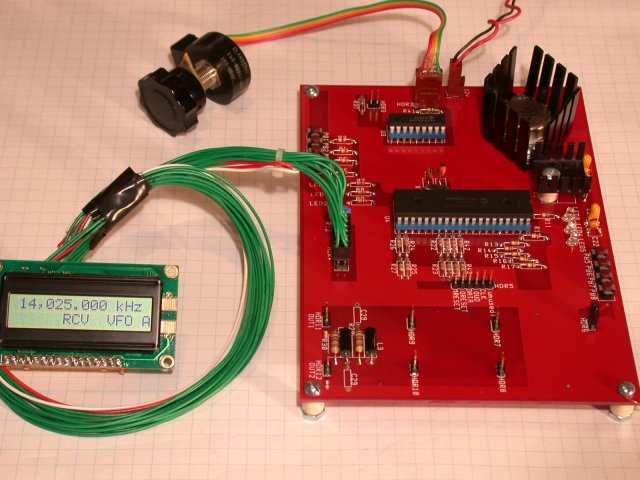
This project is an extension of the concepts introduced in that original AD9850 project, with many improvements. The IQ-VFO still has an optical encoder for frequency selection and it still uses an LCD for displaying the frequency, and it offers the following additional capabilities:
- The IQ-VFO uses two PIC microcontrollers – one controlling the optical encoder and the other controlling the AD9854, the LCD, the pushbuttons and the LEDs.
- The IQ-VFO uses a two-line LCD so more information is displayed.
- The IQ-VFO operates as two VFOs with two frequencies.
- The two-part VFO supports split-frequency operation.
- The two AD9854 outputs are amplified to produce signal levels that are compatible with common receiver requirements (such as the R2 or KK7B R2Pro Receiver project.)
Block Diagram
Schematic


Obtaining the AD9854 DDS Chip
The AD9854 DDS chip is not provided in the IQ-VFO Kit … homebrewers may obtain a free sample from the Analog Devices website at www.analog.com. Just go to this Internet location, select the Price/Packaging/Availbility link, add the AD9854AST part to your Samples Cart, and answer the simple questions they ask. Within several days or so you will receive a free sample of the DDS chip by mail. The DDS chip may also be purchased through Avnet or Future-active distributors. (Search the Internet for locations closest to you.)
Getting Kit Assembly Help
If desired, the AmQRP has lined up a great resource to assist in soldering the DDS chip and/or other SMT components onto the printed circuit board. Once you’ve acquired your AD9854 DDS chip from Analog Device, send the chip and your IQ-VFO circuit board, to Mike WA6OUW, at “KitBuilders”. For $10 he will do an expert job at soldering this large surface mount chip to the pc board and return it promptly by mail. It’s not tested because at that point it’s only the DDS chip on a bare pc board, but Mike does excellent work. (The AmQRP uses KitBuilders for assembly of the HC908 Daughtercard product, so we know the quality is there!) Just place your DDS chip, pc board and check or M.O. payable to “KitBuilders” into a padded envelope and send to: KitBuilders, 6361 Berrybush Ct., Gilroy, CA 95020. Within a week or so Mike will be able to solder on your DDS chip and return it by mail. You can contact Mike by email at [email protected] if you have further questions or if you’d like some additional assembly work done on your IQ-VFO kit.